
Tracing distortion — the pinch effect, vertical-line distortion and loss of wavelength.
If we set aside the non-linearity of electromechanical transducers (the cutting head during recording and the cartridge during playback), most of the distortions that arise during groove scanning are caused by the difference in the geometries of the recording and playback tools.
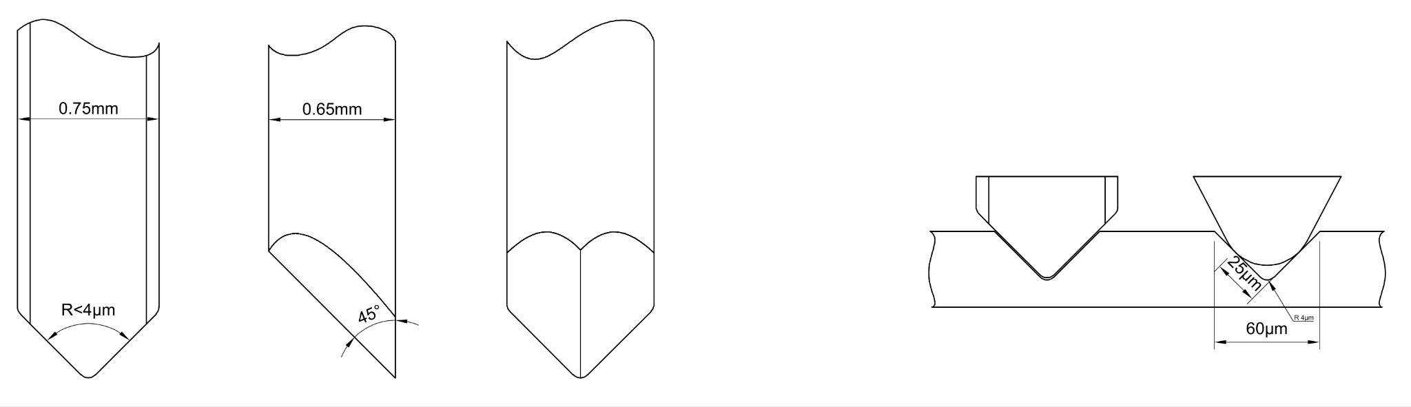
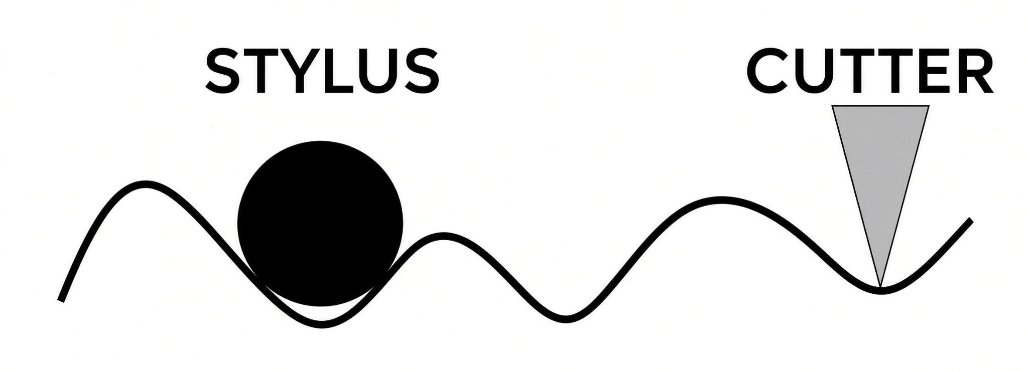
During recording on lacquer, a flat cutter driven by a moving-coil mechanism is guided along a radial line across the soft acetate disc. During playback, a conical (or elliptical) stylus supported by a cantilever moves along an arc across the plastic disc at the end of a long tonearm. This leads to the distortion mechanisms described below.
Tracing Distortion
Tracing Distortion differs from tracking distortion, which will be described in detail in the section “Tracking Distortion (lateral). The problem with using a radial tonearm that leads to a time difference between the left and right channel signals”. The origin of all tracing distortions lies in the fact that a groove cut by a flat-faced cutter is read by a rounded (conical or elliptical) stylus. Tracing distortion is responsible for the majority of distortions (not only harmonic distortions) during gramophone record playback. There are three mechanisms of tracing distortion: the pinch effect, vertical line distortion, and wavelength loss.
Pinch Effect
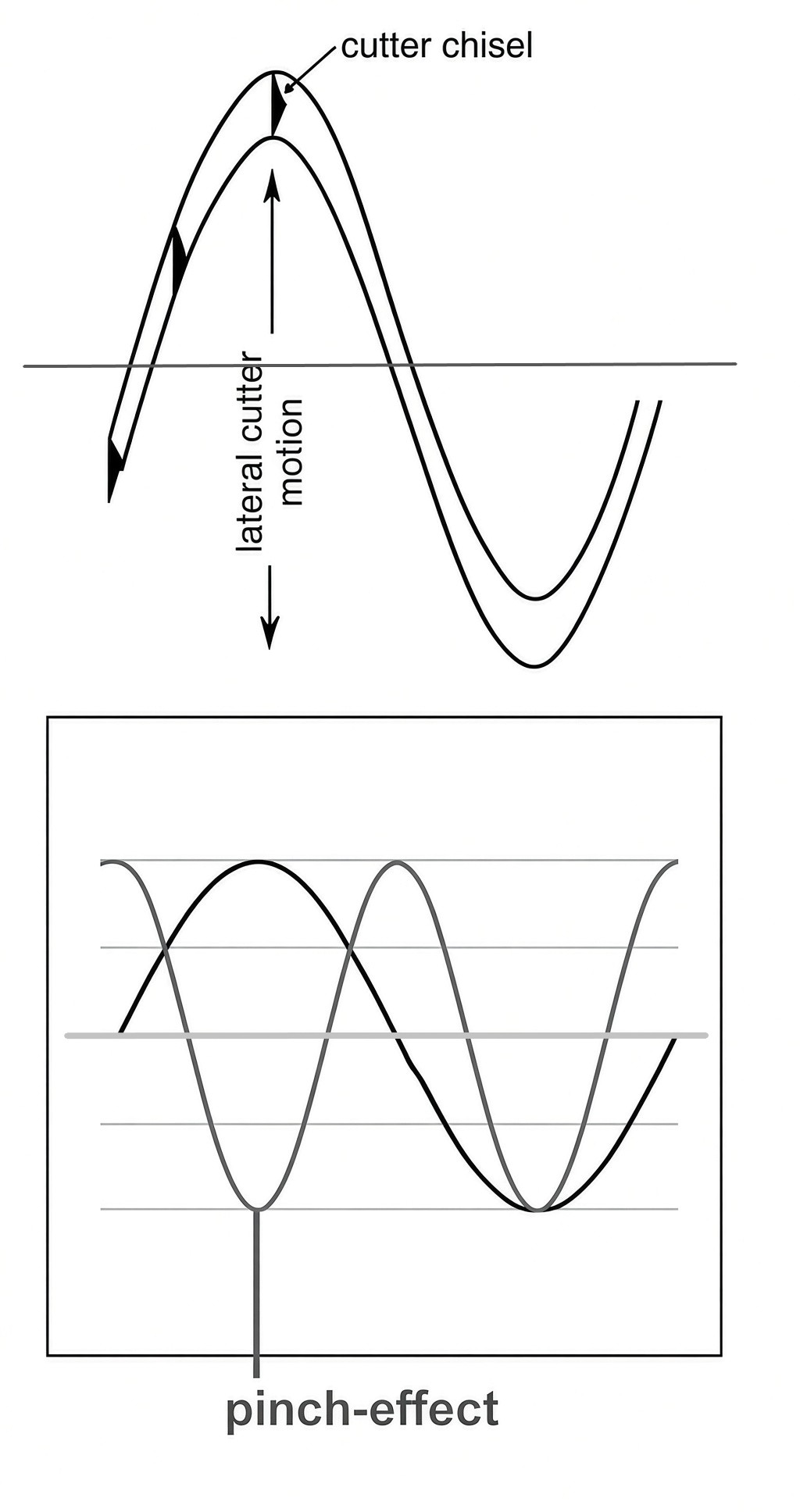
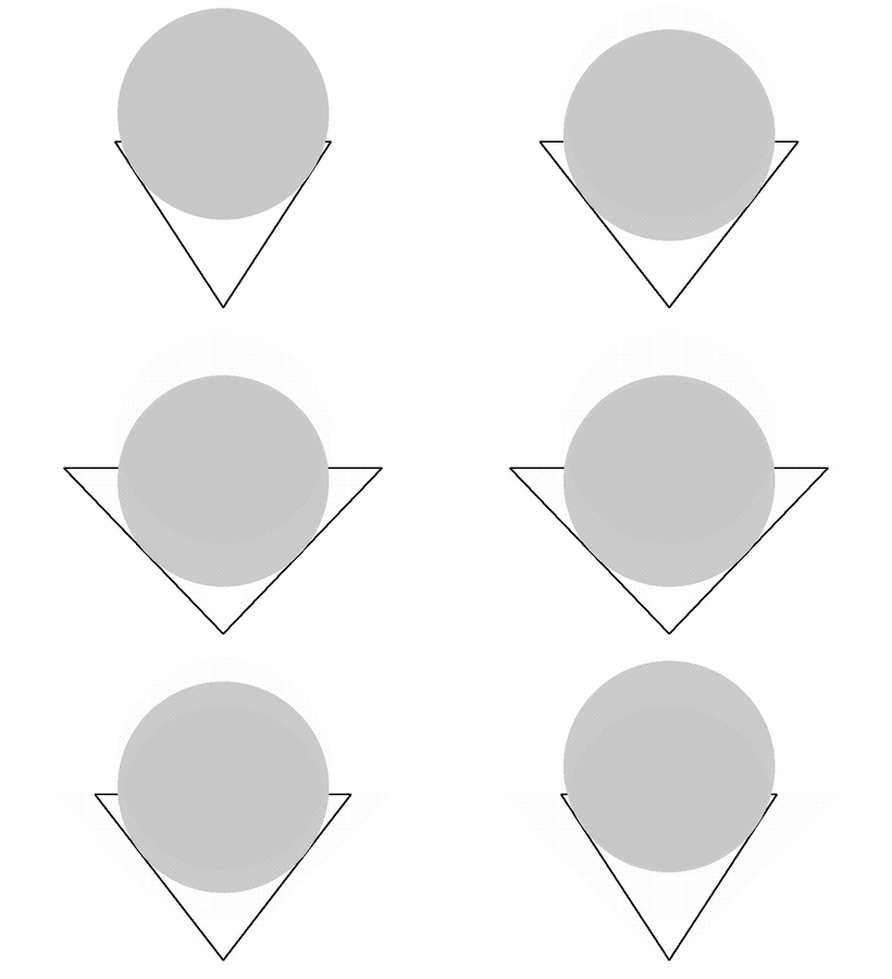
Given that the cutting stylus, forced to follow a trajectory along the radius of the disc, cuts a groove whose width equals the width of the cutter ONLY at the wave peaks, and which decreases to a minimum when the wave passes through the zero position. This creates an effect of the stylus being pinched up and down in the groove, even if the modulation is completely lateral. This phenomenon is commonly called the pinch effect.
This pinch effect (squeezing) of the stylus in the narrowing groove can be observed at a frequency twice the frequency of the lateral modulation; because the stylus rises and falls twice per cycle of the modulation wave (see illustration).
The stylus pinch effect becomes stronger as the wavelength of the modulation decreases. In addition to the wavelength depending on frequency, it is also a function of the angular velocity of the cutting stylus in the groove. On a normal record this speed drops as the cutter (or stylus) moves toward the center of the record, because the record rotates at a constant number of revolutions per minute, but the groove radius decreases during playback of one side of the record.
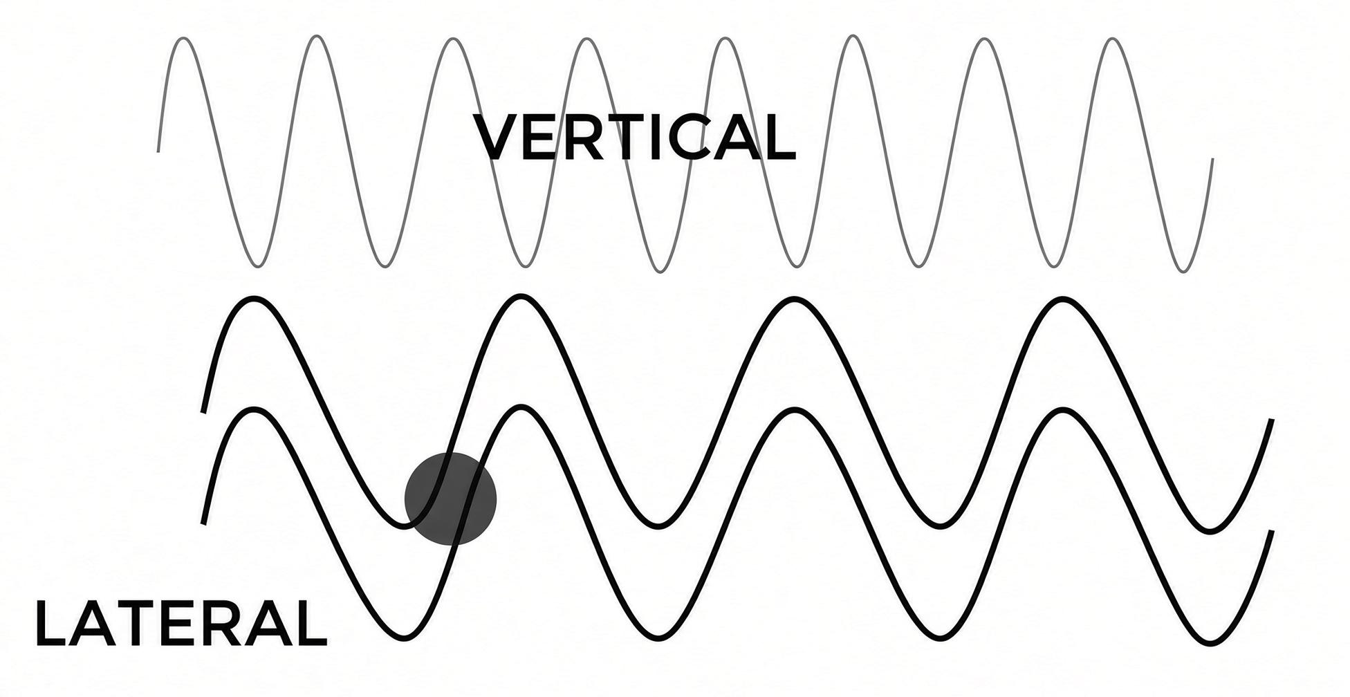
Furthermore, the degree of the pinch effect depends on the radius of the stylus in the direction of groove travel. To reduce it, an elliptical stylus shape was developed: the major axis of the ellipse is the size of a conical stylus and is oriented perpendicular to the groove. Thanks to this, the stylus contacts the walls at the same height as a conical one and does not “sink” into the bottom of the groove where there is no information. The minor axis of the ellipse is significantly smaller and is oriented parallel to the groove, so the stylus is less pinched when the groove narrows in the direction of its movement.
Vertical Line Distortion.
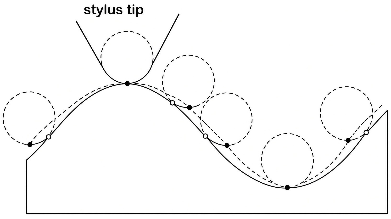
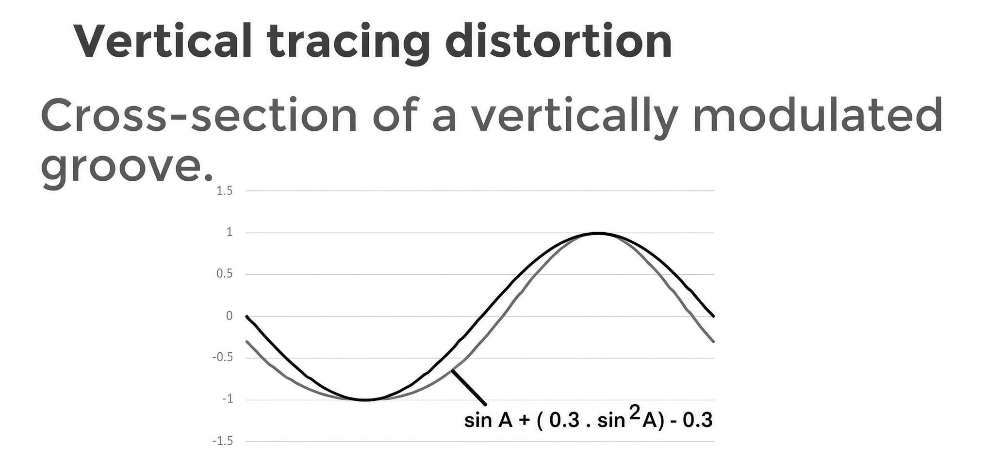
The figure shows a cross-section of a vertically modulated groove. Recording is performed with a sharp-edged cutter, while playback is performed with a spherically rounded stylus cone. The figure shows that the movement of the playback stylus does not follow the shape of the groove. The reason is that the point of contact between the spherical stylus and the groove wall shifts during tracking, forcing the stylus to move along the trajectory marked by the dashed line.
Wavelength Loss.
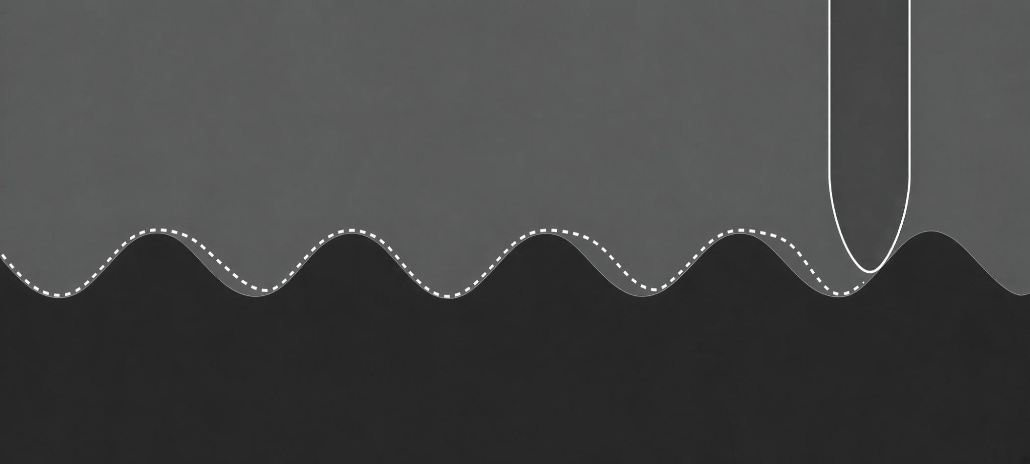
Wavelength loss (sometimes called tracing loss) is another distortion that arises because a sharp cutter is used during recording and a rounded stylus during playback. The sharp cutter is able to form “sharper corners” and shorter wavelengths than the stylus can track, leading to loss of high frequencies. Additionally, this is affected by the deformation of the soft vinyl under the pressure of the hard diamond stylus. Shorter wavelengths and stronger vinyl deformation become especially noticeable closer to the center of the record. Most cartridges, even with elliptical tips, show a roll-off in frequency response as the groove approaches the center.

Scanning Loss
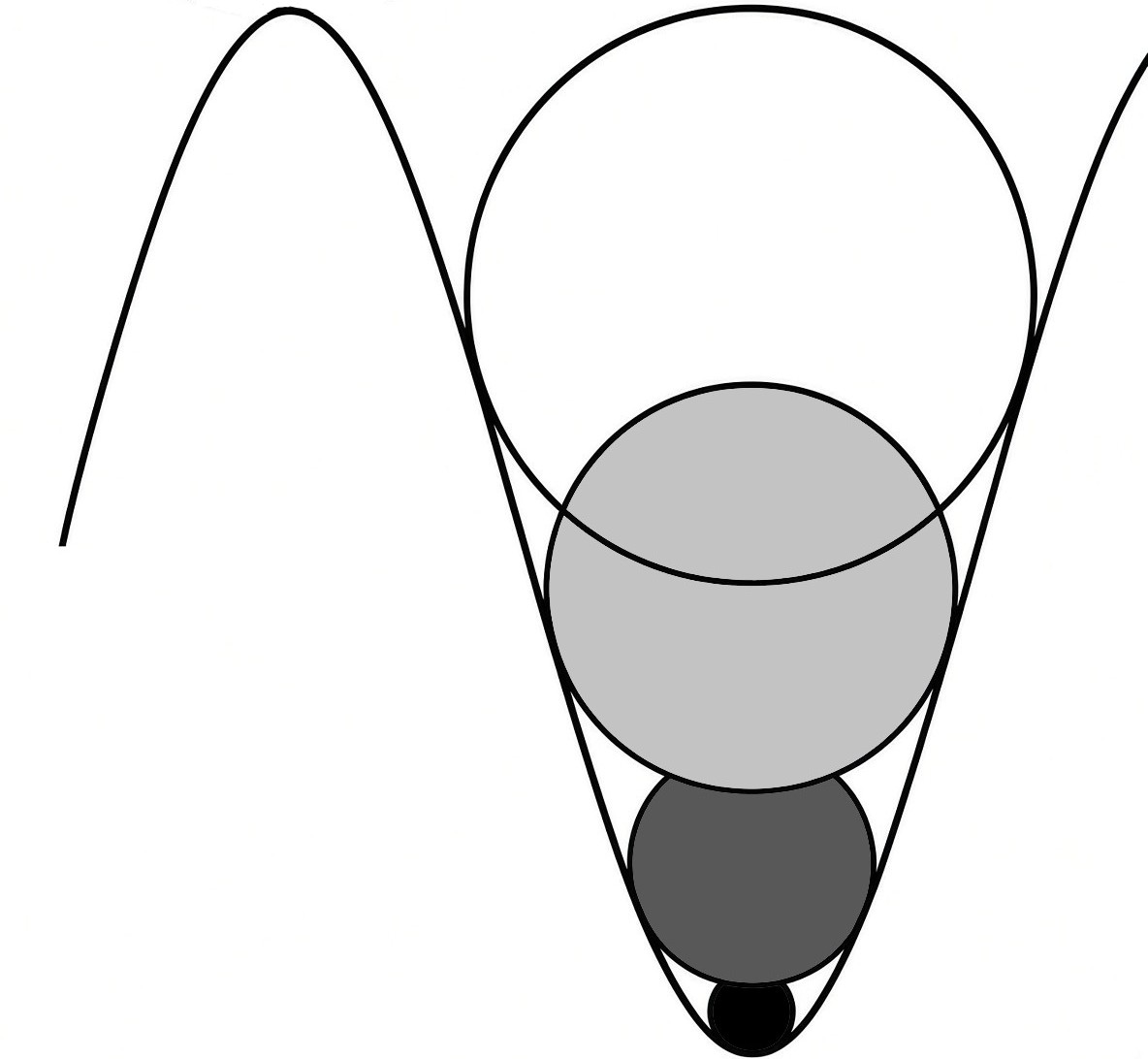
Wavelength loss is a combination of two effects. The first of these is scanning loss, which is due to the fact that a sharp cutter is used during recording and a rounded stylus during playback. The sharp cutter is able to form “sharper corners” and shorter wavelengths than the stylus can track. When the recorded wavelengths approach the size of the stylus, high-frequency loss occurs. In this case the stylus acts as a physical high-frequency filter.
Since the wavelength on the record depends on both the recorded frequency and the groove radius, scanning loss becomes especially noticeable closer to the center of the LP.
Translation Loss
The second effect is sometimes called translation loss, and it is the result of the flow of the relatively soft plastic material of the record when a hard diamond stylus passes over it. This is also wavelength-sensitive, and therefore, in combination with scanning loss, creates a greater problem for the inner grooves of the record.